
2. Yaw-Axis Torque Generation
The inclusion of a novel development, the Yaw-Axis Torque Generator, allows NPAS Odyn to operate without the use of a tailrotor. The Yaw-Axis Torque Generator applies necessary counter-torque without the addition of an asymmetric lateral force.
2.1 The Yaw-Axis Torque Generator
The Yaw-Axis Torque Generator takes the form of a modified gyroscope, that has been edited to only apply moments along its yaw axis. The settings used for Odyn’s torque generator are pasted below for the convenience of the reader:
autoOrient = true
stability = 0
speed = 0
yawPower = 35
pitchRange = 0
rollRange = 0
When such settings are used, the gyroscope cannot attempt to correct roll/pitch orientation. Instead, the gyroscope can only provide yaw-axis torque.
As stated, the inclusion of a Yaw-Axis Torque generator negates the need for a tailrotor. Therefore, no unnecessary lateral forces are applied onto the helicopter.
2.2 Facilitating Yaw-Axis Stability Via Torque Generator
When implemented practically, the Yaw-Axis Torque Generator is programmed to counteract torques produced by the main rotor, as well as provide yaw-control torques. Simultaneous tasks are accomplished by assigning portions of the Yaw-Axis Torque Generator’s power to each task. In the case of NPAS Odyn, 50% of the torque generator is used to counteract main rotor moments, while the other 50% is used to facilitate yaw-axis control. The resulting code is pasted below for the convenience of the reader:
Yaw + 0.5 * (-1 * clamp(YawRate, -1, 1) * clamp01(abs(YawRate) > 0.001) )
The code uses a standard structure, that negates the use of a PID controller. Instead, simple clamp logic, and an appended negligible case, accomplish the given task adequately.
3. The ARC Flight System
The Automated Rotor Control (ARC) flight system provides a variety of corrections based on the input of the user. In its current state, the system can maintain a positive stability (will be defined in section 3.1), maintain an orientation lock, and provide velocity corrections using a vector approach. The system accomplishes these functions using a gyroscope as well as its main rotor. For brevity, all code will only be discussed at a high level. Hopefully, the code, as pasted below, will explain the reasoning for such a decision, as well as be sufficient for the reader to use:
Rotor Roll Control:
clamp01(-1 * Activate4) * Roll + clamp01(-1 * Activate3) * 0.2 * ( Activate1 ? clamp(RollAngle, -1, 1) * clamp01(abs(RollAngle) > 0) * clamp01(abs(RollAngle) > 0.1) : (clamp(rate(RollAngle), -1, 1) * clamp01(abs(rate(RollAngle)) > 0) * clamp01(abs(rate(RollAngle)) > 0.1) * clamp01(Activate2) ))
Rotor Pitch Control:
Pitch * clamp01(-1 * Activate4) = 0 & -1 * Activate3 ? ( ( Activate1 ? (0.2) * clamp(PitchAngle, -1, 1) * clamp01(abs(PitchAngle) > 0) * clamp01(abs(PitchAngle) > 0.1) : 0.8 * (clamp(rate(PitchAngle), -1, 1) * clamp01(abs(rate(PitchAngle)) > 0) * clamp01(abs(rate(PitchAngle)) > 0.001) * clamp01(Activate2) ) )) : Pitch
Gyroscope Roll Control:
2 * smooth(Roll, 1/3) + smooth(-1 * sign(AngleOfSlip) * clamp01(abs(GS * cos(AngleOfAttack + PitchAngle) * sin(AngleOfSlip) )) , abs(GS * cos(AngleOfAttack + PitchAngle) * sin(AngleOfSlip) ) > 0.1 ? 1/10 : pow(10,10) ) * clamp01(abs(GS * cos(AngleOfAttack + PitchAngle) * sin(AngleOfSlip)) > 0.1)
Gyroscope Pitch Control:
2 * smooth(Pitch, 1/3) + smooth(clamp(-1 * GS * cos(AngleOfAttack + PitchAngle) * abs(cos(AngleOfSlip)), -1, 1), abs(GS * cos(AngleOfAttack + PitchAngle) * abs(cos(AngleOfSlip)) ) > 0.1 ? 1/10 : pow(10,10) ) * clamp01(abs(GS * cos(AngleOfAttack + PitchAngle) * abs(cos(AngleOfSlip))) > 0.1)
It is important to note that the gyroscope is only needed for velocity correction. Velocity correction is an extra feature that, while useful, is not necessary for the other functions of the ARC flight system. It should also be noted that much of the provided code is entry-level, and can be improved through minor iteration, as will be discussed in section 3.4.
3.1 Defining and Maintaining Positive Rotor Stability
In the case of the ARC system, positive stability is characterized by the aircraft naturally returning to an upright position (pitchAngle = RollAngle = 0) without user input. The ARC system’s first flight mode facilitates positive stability by automatically making small corrections keep to the aircraft level. Corrections are made using collective pitch and roll control given the absence of user input.
Code-wise, the system uses a standard structure that employs ‘all or nothing’ methodology. If the user is providing input, then the automatic flight system will pause its operation. The automatic flight system continues to operate when the user stops providing pitch/roll input. This logic is used so the user does not ‘fight with’ the automatic flight system.
3.2 A High-Level View of Orientation Lock Logic
From a purely mathematical standpoint, the implementation of an orientation lock is simply the mathematical derivative of the ARC system’s positive stability flight mode. An orientation lock is achieved by setting the rollRate and pitchRate equal to zero. Figure 3.1.1 shows this relation in graphical form:
Figure 3.1.1: Differentiating the control system
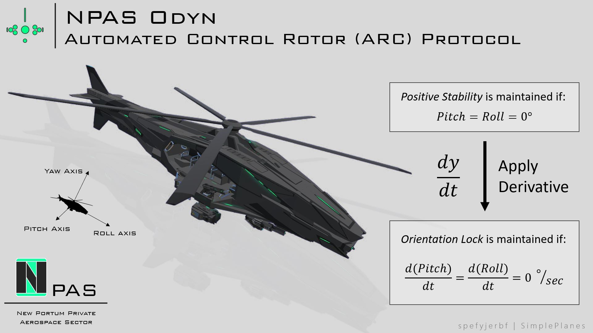
When implemented as code, the orientation lock subroutine also employs ‘all or nothing’ methodology. Extra modifiers, too, are introduced to avoid interference with other flight modes, including the positive stability subroutine.
3.3 A Vectored Approach to Velocity Adjustment
Many automatic VTOL systems, including the 2D AUTOTOL system, are able to make adjustments that, effectively, “zero” the aircraft’s horizontal velocity. The ARC system translates such logic in a way that is applicable to a rotor system. Therefore, NPAS Odyn can automatically make corrections that will result in a horizontal ground speed of zero.
The system itself uses velocity vectors to describe the lateral and longitudinal components of the helicopter’s velocity. A gyroscope tilts the helicopter to counter such velocities. As a result, a portion of the helicopter’s lift is used to counteract the helicopter’s horizontal velocity. Similar systems exist, but the ARC flight system’s velocity adjustment subroutine is unique in that it uses a single part (a gyroscope) to function. The velocity vector approach facilitates this part efficiency.
It is important to note that this is an entry-level model. Smooth functions are used to govern the operation of the gyroscope. The system, though, is functional on larger helicopter models such as NPAS Odyn. Section 3.4 will discuss potential avenues of improvement regarding the ARC flight system.
3.4 Suggestions for Further Improvement
A rotorcraft presents unique challenges, with unique answers that differ from solutions posed by existing automatic flight systems. As a result, the ARC flight system is not perfect. In particular, the system’s positive rotor stability and velocity correction protocols can be improved.
Both protocols are flawed due to latency. The protocols indirectly accomplish their goals. In other words, each protocol employs a two-step approach. Instead of the system output itself acting as the flight correction, the system’s output leads to a secondary action, that is the flight correction. Figure 3.4.1 elaborates on this logic:
Figure 3.4.1: Control system output is not one-to-one
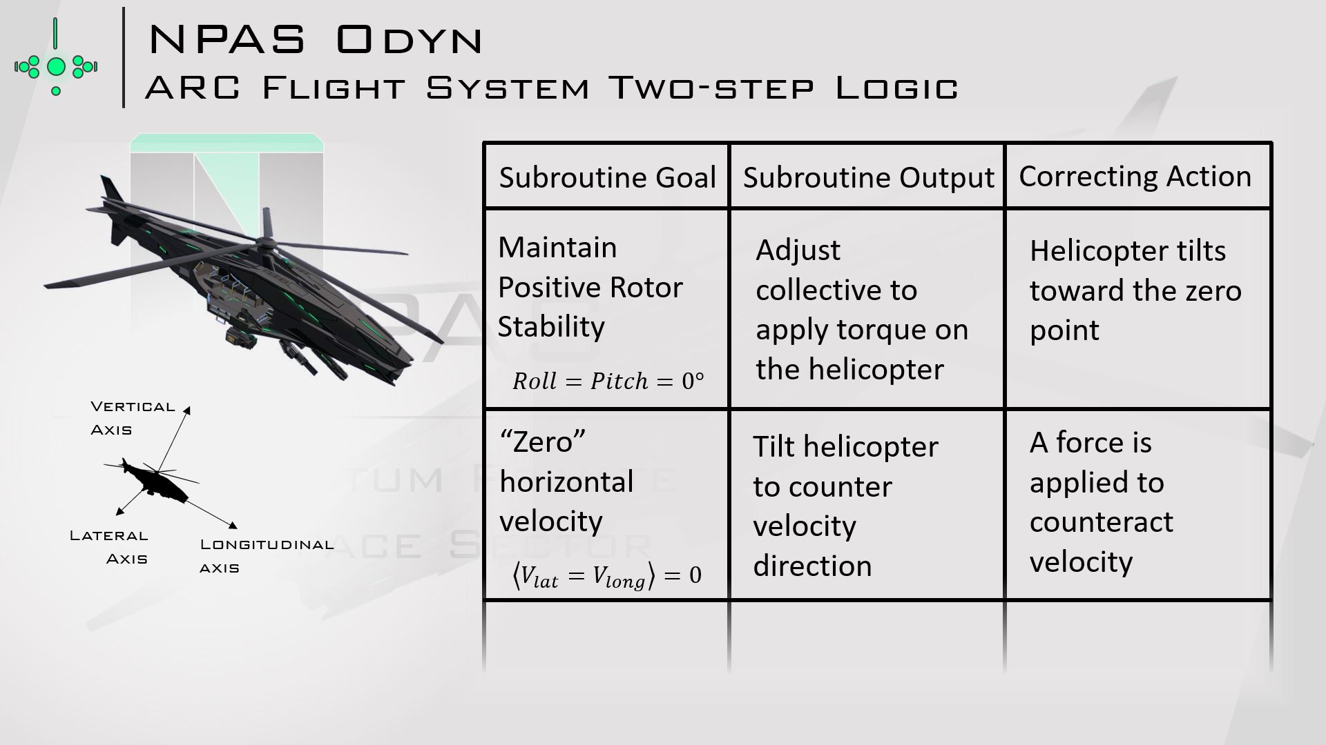
As a result, the ARC flight system does not produce an output that immediately translates to a flight correction. This disconnect propagates latency, in which there is a delay in the control system. Latency is inevitable in every control system, but it can be mitigated with better-informed control methodology.
In the case of the ARC system, the magnitude of each correction can be edited to be proportional to the magnitude that the correction requires. Such an improvement would alleviate problems caused by the system’s latency, which would significantly improve the system’s performance. Code-wise, the lerp function would suffice. Interpolation logic, in this case, would ensure proportional response to each necessary flight correction.
This posts contains documentation for an upcoming build. If you want me to tag you in the upload, let me know!
@atgxtg No problem! Tag me when you upload your autogyro so I can check it out :)
@spefyjerbf Thanks, you solved both of my autogyro prerotator problems with your example! Now I can prerotate the blades without torque, and get the prerotator to automatically disengage when I start the actual engine.
@hpgbproductions The font is one of the built-ins in MS PowerPoint. I think it’s called “Bancgothic” or something like that. The AGs let you specify which flight mode you want to be in.
That
sumreal algebruh here.Uhmm.
Clears throat
Torque
That's a lot of words for auto stability control
What do the AGs do?
On a side note can i get the sauce of that font lol
oh dear, what have i come into, this solution, is absurd
@SnoWFLakE0s Ty!
Cool maths
@asteroidbook345 relatable
Tag please
I only have 1 braincell and can't understand this