
2. The Differential Electric Engine
Edo-45 was designed around a novel electric engine, named the Differential Electric Engine. The engine employs phase-shifted pistons, reverse-airbrakes, and code derived from a differential equation to produce a nearly-logistic velocity curve. The overall design process focuses on the velocity curve's end behavior, as velocity has been designed to approach a ceiling asymptotically.
2.1 Acceleration as a Differential Equation
Airbrake-based electric engines must be designed to limit their maximum velocity. Many mechanisms can be used to limit maximum velocity, but no existing methods explicitly define a maximum velocity in a gradual fashion. In other words, the few engines that do define a velocity ceiling, within their code, only do so through logical operators - resulting in a rather bumpy velocity curve.
The Differential Electric Engine explicitly defines its maximum velocity, gradually, by using a differential equation. In particular, a differential equation with an equilibrium solution, set to the engine's velocity ceiling, was used. This equation is the foundation of the Differential Electric Engine, and is used to govern the engine's force output. Change in velocity, after all, is defined as acceleration, and is proportional to net force. Therefore, the differential equation (general form), as well as its solution, found in Figure 2.1.1, is valid for use in the Differential Electric Engine:
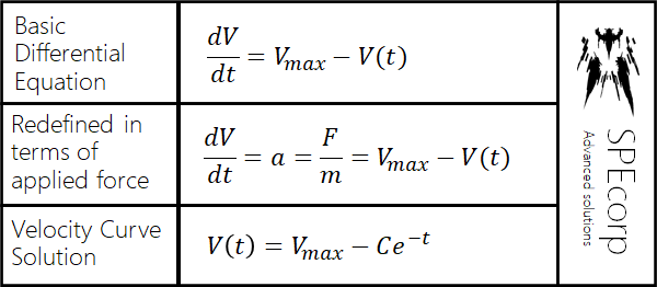
Figure 2.1.1: The Engine's Differential Equation
The variables, as shown in the figure, are defined below:
V_max= The velocity ceiling, maximum velocity
V(t)= The time-varying velocity curve, velocity function. It is the dependent variable
t= The independent time variable
a= The acceleration
F / m= The force divided by mass
C= An arbitrary constant (depends on initial value)
The differential equation, then, can be applied in the form of code, that will govern the force output of the reverse-airbrake system. Section 2.2 details such application.
2.2 Implementation and Practical Considerations
The differential equation is applied by translating it into code. The code is then edited to prevent overcorrection and to enable throttleability. Overcorrection is prevented by using a clamp function, that prevents negation, and limits the maximum force output of the engine. Throttleability is achieved by multiplying the velocity ceiling by a throttle input. As a result, the velocity curve becomes a family of curves with throttle-varying maximum velocities, as shown in figure 2.2.1:
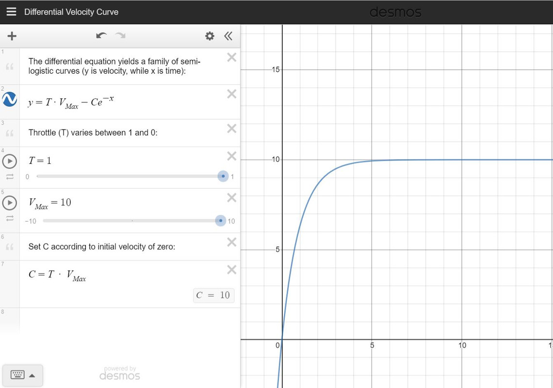
Figure 2.2.1: Velocity Curve Family (Click for the Animated Version)
The input code, with these applied changes, is provided below in a general form:
-1 * clamp(Throttle * V_Max - 1 * GS * cos(AngleOfAttack) * cos(AngleOfSlip), 0, Max_Output )
Where:
V_Max= The designed maximum velocity
Max_Output= The maximum output of the engine. This value is proportional to the maximum force output of the engine. This value is less than or equal to the maximum velocity,V_max.
This code should be used as the input of an airbrake. The minimum input of the airbrake, min, should be set to a (usually small) negative number, that can be tweaked to adjust the engine's force output. It should be noted that the code uses the longitudinal component of the aircraft's velocity. Negation is applied, too, as the reverse-airbrake accepts negative inputs to generate thrust.
Reverse airbrakes require velocity to apply force. The engine, then, uses pistons to provide necessary velocity to the airbrakes (credit: randomusername). The Differential Electric Engine itself uses a pair of such pistons. The piston pair employs a phase shift to provide a smooth flight experience. A reverse airbrake is attached to the end of each piston. The specifications of each piston are as follows:
Piston Number One
input: -1 * (Throttle = 0) * (1 + cos(Time * 9000))
range: 1
speed: 100
preventBreaking: true
Piston Number Two
input: -1 * (Throttle = 0) * (1 - cos(Time * 9000))
range: 1
speed: 100
preventBreaking: true
Note that an airbrake should be attached to each piston. These two airbrakes are identical, and use the code discussed earlier in this section. The engine can be tweaked in three ways to meet the programmer's requirements:
- Edit the velocity ceiling,
V_Max.- Edit the maximum engine output,
Max_Output.- Edit the minimum input,
min. A larger magnitude will yield a larger force. -0.3 yields a small force, while -100 yields a ridiculously large force.
To reiterate, the code for both airbrakes is as follows:
-1 * clamp(Throttle * V_Max - 1 * GS * cos(AngleOfAttack) * cos(AngleOfSlip), 0, Max_Output )
The minimum input is named min, under the inputController tab in overload.
As a result, the Differential Electric Engine is highly customizable for the experienced programmer. This characteristic, among others, will be expanded upon in section 2.3.
2.3 Advantages of the Differential Electric Engine
As previously mentioned, the Differential Electric Engine sets a limiting velocity in a gradual fashion. This approach results in a smooth velocity curve that is explicitly defined. Existing reverse-airbrake engines do not meet this functional requirement. Instead, they either set a limiting velocity, or they provide a smooth velocity curve that lacks an explicit velocity ceiling.
The former approach (unsmoothed velocity regulation) simply uses logical operators, which results in an all-or-nothing engine behavior. The engine either applies its maximum force, or no force at all. This behavior causes this approach to be sub-optimal at best. The latter approach (smooth, yet undefined velocity curve), in contrast, is actually quite useful. This approach, which gradually decreases acceleration, takes the form of the following airbrake input code:
pow(0.99, GS) [Source]
The force output of this engine, then, is governed by a negative exponential function. As a result, this entry-level engine will be referred to as the "negative exponentional engine". If viewed as a differential equation, this existing function yields a logarithmic velocity curve. An equilibrium velocity is reached implicitly when, ironically, drag acts on the aircraft. These two functions appear to be similar when graphed, as in figure 2.3.1:
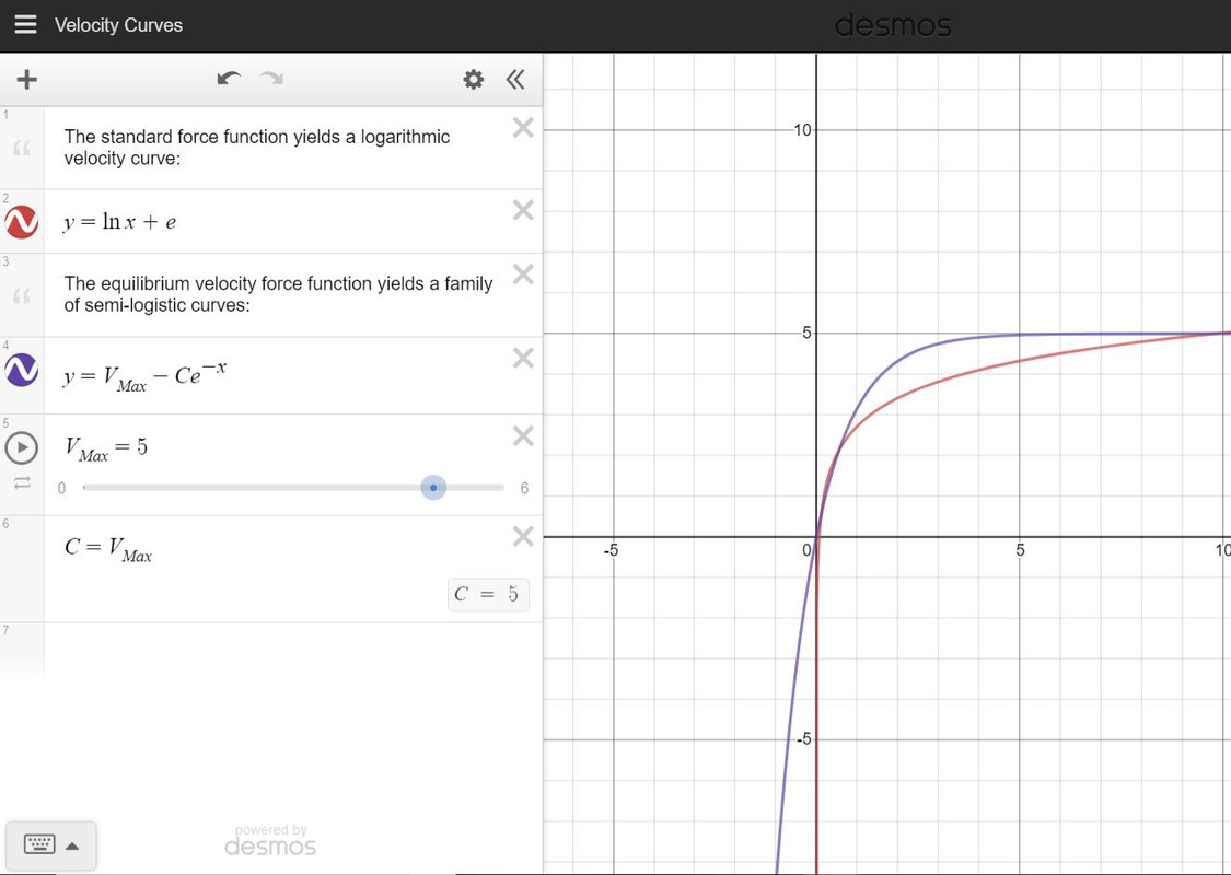
Figure 2.3.1: Velocity Curve Comparison (Click for the Animated Version)
In a practical setting, though, the Differential Electric Engine becomes advantageous through two characteristics:
Benefit One:The engine explicitly defines a maximum velocity
Benefit Two:The engine is more customizable than other existing engines.
The first benefit is, admittedly, a preference that may vary among programmers. It should be noted, though, that an explicitly defined maximum velocity may decrease the amount of fine tuning needed to design a proper electric aircraft.
Benefit Two, though, hinges on the versatility of the Differential Electric Engine. The system can be configured to meet a wider variety of operating conditions than its negative exponential counterpart. The Differential Electric Engine presents three parameters that the programmer can modify to meet their design specifications:
- The ceiling velocity can be modified
- The maximum engine output can be clamped
- The overall engine output can be modified
In theory, the Differential Electric Engine can be configured to govern its maximum acceleration, velocity, and average engine output. In contrast, the negative exponential engine is commonly configured by simply changing its average force output. As a result, the Differential Electric Engine can be configured to meet a wider array of operating conditions than its negative exponential counterpart.
This post is part of Edo-45's technical documentation. Use the link to return to Edo-45.
@Ezucra No problem! Have fun with the concept :)
Thank you so much Spef! Will definitely work with this in the future.
Sees equations Confused screaming
Didn't know simpleplanes could get so, not simple
@MercuryCorporation Sounds good, and ty! Building from scratch is definitely more satisfying, so you’re right on that point. When talking to people about this engine, I assume that they aren’t familiar with calculus (or diffeq), so I default to having them take the engine as a subassembly.
@MercuryCorporation Go for it! Feel free to rip the engine out of Edo-45 and save it to your subassemblies. Please not that, with any upload that involves this specific engine design (mainly the Funky Trees that I used), I do appreciate credit where appropriate.
Holy...
@BaconAircraft I agree, ty!
Simply beautiful
@Tums Ty! This one was a wild ride, and I'm quite proud of the math behind it.
I haven’t read all this, but your derivative equations are spot on. This is really impressive!
Hi everyone,
.
This forum post is part of my next upload's technical documentation. As of posting this comment, the build has not been released. You can find the teaser here.