
Credit to: 421stFighterSquadron’s NATF
Edit:it works just don’t use yaw trust me ok.
I mean it… “flies”
Wiki YF-23: The Northrop/McDonnell Douglas YF-23 is an American single-seat, twin-engine, supersonic stealth fighter aircraft technology demonstrator designed for the United States Air Force (USAF). The design was a finalist in the USAF's Advanced Tactical Fighter (ATF) competition, battling the Lockheed YF-22 for a production contract. Two YF-23 prototype air vehicles were built. In the 1980s, the USAF began looking for a replacement for its fighter aircraft to more effectively counter the USSR's advanced Sukhoi Su-27 and Mikoyan MiG-29. Several companies submitted design proposals; the USAF selected proposals from Northrop and Lockheed. Northrop teamed with McDonnell Douglas to develop the YF-23, while Lockheed, Boeing, and General Dynamics developed the YF-22.The YF-23 was stealthier and faster, but less agile than its competitor. After a four-year development and evaluation process, the YF-22 was announced the winner in 1991 and developed into the Lockheed Martin F-22 Raptor, which first flew in 1997 and entered service in 2005. The U.S. Navy considered using the production version of the ATF as the basis for a replacement to the F-14, but these plans were later canceled. The two YF-23 prototypes are currently museum exhibits.
Design: The YF-23A (internally designated DP117K) was an unconventional-looking aircraft, with diamond-shaped wings, a profile with substantial area-ruling to reduce aerodynamic drag at transonic and supersonic speeds, and an all-moving V-tail.[6] The cockpit was placed high, near the nose of the aircraft for good visibility for the pilot. The aircraft featured a tricycle landing gear configuration with a nose landing gear leg and two main landing gear legs. The weapons bay was placed on the underside of the fuselage between the nose and main landing gear.[21] The cockpit has a center stick and side throttle.[22]
Development: American reconnaissance satellites first spotted the advanced Soviet Su-27 and MiG-29 fighter prototypes in 1978, which caused concern in the U.S. Both Soviet models were expected to reduce the maneuverability advantage of contemporary US fighter aircraft.[1] In 1981, the USAF requested information from several aerospace companies on possible features for an Advanced Tactical Fighter (ATF) to replace the F-15 Eagle. After discussions with aerospace companies, the USAF made air-to-air combat the primary role for the ATF.[2] The ATF was to take advantage of emerging technologies, including composite materials, lightweight alloys, advanced flight-control systems, more powerful propulsion systems, and stealth technology.[3] In October 1985, the USAF issued a request for proposal (RFP) to several aircraft manufacturers. The RFP was modified in May 1986 to include the evaluation of prototype air vehicles from the two finalists.[N 1] At the same time, the U.S. Navy, under the Navalized Advanced Tactical Fighter (NATF) program, announced that it would use a derivative of the ATF winner to replace its F-14 Tomcat. The NATF program called for the procurement of 546 aircraft along with the USAF's planned procurement of 750 aircraft.[4]
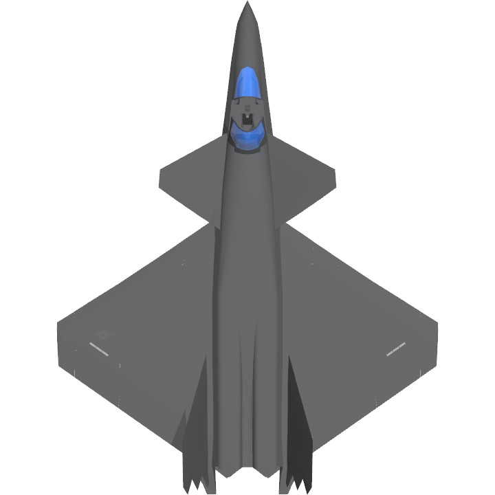
Top view of black jet aircraft, showing trapezoidal wings, engine nozzle, and two-piece tail. The separation between the forward fuselage and engine nacelles is apparent.
Top view of the YF-23, showing the trapezoidal wings and separation between the forward fuselage and engine nacelles
In July 1986, proposals for Demonstration and Validation (Dem/Val) were submitted by Lockheed, Boeing, General Dynamics, McDonnell Douglas, Northrop, Grumman and Rockwell; the latter two dropped out of competition shortly thereafter.[5] Northrop’s design proposal (DP) was internally designated DP110.[6] Following proposal submissions, Lockheed, Boeing, and General Dynamics formed a team to develop whichever of their proposed designs was selected, if any. Northrop and McDonnell Douglas formed a team with a similar agreement.[7] The Lockheed and Northrop proposals were selected as finalists on 31 October 1986 for Dem/Val. Both teams were given 50 months to build and flight-test their prototypes, and they were successful, producing the Lockheed YF-22 and the Northrop YF-23. Concurrently, Pratt & Whitney and General Electric were contracted to develop the engines for the ATF engine competition.[8]
The YF-23 was designed to meet USAF requirements for survivability, supercruise, stealth, and ease of maintenance.[9] Supercruise requirements called for prolonged supersonic flight without the use of afterburners.[10] Northrop drew on its experience with the B-2 Spirit and F/A-18 Hornet to reduce the model's susceptibility to radar and infrared detection.[11] The USAF initially required the aircraft to land and stop within 2,000 feet (610 m), which meant the use of thrust reversers on their engines. In 1987, the USAF changed the runway length requirement to 3,000 feet (910 m), so thrust reversers were no longer needed. This allowed the aircraft to have smaller engine nacelle housings. The nacelles were not downsized on the prototypes.[12][13]
Formally designated as the YF-23A, the first aircraft (serial number 87-0800), Prototype Air Vehicle 1 (PAV-1), was rolled out on 22 June 1990;[14] PAV-1 took its 50-minute maiden flight on 27 August with Alfred "Paul" Metz at the controls.[15] The second YF-23 (serial number 87-0801, PAV-2) made its first flight on 26 October, piloted by Jim Sandberg.[16] The first YF-23 was painted charcoal gray and was nicknamed "Spider". The second prototype was painted in two shades of gray and nicknamed "Gray Ghost".[17] PAV-1 briefly had a red hourglass painted on its ram air scoop to prevent injury to ground crew. The red hourglass resembled the marking on the underside of the black widow spider further reinforcing the unofficial nickname "Black Widow II" given to the YF-23 because of its radar cross section plot shape that resembled a spider. When Northrop management found out about the marking, they had it removed.[18]
Naval variant
A proposed naval variant of the YF-23 known as the NATF-23 was considered as an F-14 Tomcat replacement. The original YF-23 design was first considered but would have had issues with flight deck space, handling, storage, landing, and catapult launching reasons requiring a different design.[19] A NATF-23 wind tunnel test model DP527, tested for 14,000 hours, was donated by Boeing in 2001 to the Bellefontaine Neighbors Klein Park Veterans Memorial.[20]
A rear view of a YF-23, showing its tile-lined exhaust channels
It was powered by two turbofan engines with each in a separate engine nacelle with S-ducts, to shield engine axial compressors from radar waves, on either side of the aircraft's spine.[23] The inlets were trapezoidal in frontal profile, with special porous suction panels in front to absorb the turbulent boundary layer and vent it over the wings. Of the two aircraft built, the first YF-23 (PAV-1) was fitted with Pratt & Whitney YF119 engines, while the second (PAV-2) was powered by General Electric YF120 engines. The aircraft featured single-expansion ramp nozzles (SERN) and unlike the YF-22, does not employ thrust vectoring.[12] As on the B-2, the exhaust from the YF-23's engines flowed through troughs lined with tiles that are “transpiration cooled” to dissipate heat and shield the engines from infrared homing (IR) missile detection from below.[11] The YF-23's propulsion and aerodynamics enable it to supercruise at over Mach 1.6 without afterburners.[24]
YF-23 S-duct engine air intake
The flight control surfaces were controlled by a central management computer system. Raising the wing flaps and ailerons on one side and lowering them on the other provided roll. The V-tail fins were angled 50 degrees from the vertical. Pitch was mainly provided by rotating these V-tail fins in opposite directions so their front edges moved together or apart. Yaw was primarily supplied by rotating the tail fins in the same direction. Test pilot Paul Metz stated that the YF-23 had superior high angle of attack (AoA) performance compared to legacy aircraft, with trimmed AoA of up to 60°.[25] Deflecting the wing flaps down and ailerons up on both sides simultaneously provided for aerodynamic braking.[26] To keep prototyping costs low despite the novel design, a number of "commercial off-the-shelf" components were used, including an F-15 nose wheel, F/A-18 main landing gear parts, and the forward cockpit components of the F-15E Strike Eagle.[11][16]
Production F-23
The proposed production F-23 configuration (DP231 for the F119 engine and DP232 for the F120 engine) for full-scale development, or Engineering and Manufacturing Development (EMD), would have differed from the YF-23 prototypes in several ways. Instead of a single weapons bay, the EMD design would instead have two tandem bays in the lengthened forward fuselage, with the fore bay designed for short range AIM-9 missiles; an M61 rotary cannon would be installed on the left side of the forward fuselage. The aircraft's overall length was slightly increased, volume was expanded, the nose was enlarged to accept mission systems, including the radar, and the forebody chines were less pronounced and raised to the same height as the leading edge of the wing. The deletion of thrust reversers enabled the engine nacelles to have a smaller, more rounded cross-section and the space between them filled in to preserve area-ruling. The inlet design changed from the trapezoidal profile with suction panels to a semicircular compression bump. The fuselage and empennage trailing edge pattern would also have fewer serrations and the engine thrust lines were toed in at 1.5° off center[27]
NATF-23
The naval NATF-23 variant, the schematics of which surfaced in the 2010s, was different in many ways; the diamond wings were located as far back as possible, and the aircraft has conventional canted vertical tails instead of the ruddervator with serrations for low RCS and increased maneuverability at low speeds for aircraft carrier operations, folding wing capability for flight deck storage, reinforced landing gear, tailhook and canards for landing on aircraft carriers and thrust vectoring nozzles.[28] The intakes were also different as they were a quarter circle with serrations, with a bumped compression surface. The NATF-23 had an increased 48 ft wingspan while length was reduced to 62 ft.[29]
History NATF-23: The Northrop/McDonnell Douglas YF-23 was the unsuccessful entry in the Advanced Tactical Fighter (ATF) competition, which was won by the Lockheed Martin YF-22.
The Advanced Tactical Fighter (ATF) project was conceived in the early years of the Reagan administration. It was pictured as being the aircraft which would replace the McDonnell Douglas F-15 Eagle in USAF service. At that time, it was anticipated that the ATF would be ready in time to start entering service in the late 1990s, with the ATF being the primary fighter in service with the USAF by the time the new century began.
In 1969-70, even before the F-15, F-16 and A-10 had entered service with the USAF, the Tactical Air Command funded a study known as TAC-85 to begin exploring what their successor might look like. The results of this study led to TAC issuing a Concept of Operations in 1971 for what they called the Advanced Tactical Fighter (ATF). At that time, the ATF concept was still fairly vague, and there were some small-scale studies carried out during the early 1970s. In early 1975, the USAF Systems Command developed a plan to build two sets of ATF prototypes in 1977-81, but there were no funds available to fund such a project at that time.
By 1976, these studies had begun to consider the incorporation of low-observable technology in the design of the ATF. In addition, the ability to cruise at supersonic speeds without using afterburning was also considered as being important. In 1978, the USAF defined two separate projects, one known as the Enhanced Tactical Fighter (ETF) and the other known as the Advanced Tactical Attack System (ATAS). The ETF would be a near-term project, whereas the ATAS would be a longer-term project which would concentrate on the development of new weapons and other advanced technologies. Initially, the emphasis would be on the ground-attack mission, since it was assumed that the F-15 and F-16 would be able to deal adequately with the Soviet fighters then in service. However, the appearance of new Soviet fighter such as the MiG-29, Su-27, and the MiG-31 caused the USAF to reconsider its philosophy and consider the development of air-to-air and air-to-ground aircraft in parallel. In April of 1980, the ETF project was shelved, and the ATAS became the ATF. The ATF would consider both types of missions. It was hoped that both air-to-air and air-to-ground roles could be incorporated in the same aircraft. In addition, it was decided that that the possibility of incorporating STOL into the design should also be explored.
The first Request For Information (RFI) for the Advanced Tactical Fighter was issued to the industry in June of 1981. Nine companies were involved in the RFI: Boeing, Fairchild, General Dynamics, Grumman, Lockheed, McDonnell Douglas, Northrop, Rockwell, and Vought. An RFI for the engine was issued a month later. The RFI was basically a request from the Air Force for the industry to tell them what the requirements for the new aircraft should be. Seven companies responded to the RFI. By October 1982, the USAF had digested the RFI responses that came in and decided that supercruise capability would be an important requirement for the future ATF. NATO commanders had expressed pessimism about the survivability of forward-based NATO fighter and attack forces should a war break out in Europe. Control of the skies above central Europe would probably have to be maintained by fighters based in the Benelux countries or in the United Kingdom. In such a scenario, the ability of an aircraft to fly at supersonic speed without afterburning and thus to fly supersonically for the entire mission segment that lay over hostile territory would, it was hoped, reduce the fighter's exposure to enemy SAMs. Short Take-Off and Landing (STOL) capabilities would also be important, since STOL would make it easier to continue operations from damaged airfields. It was also recommended that the aircraft should have a greater range than that of the F-15, which would allow it to operate from more distant, safer airbases. In addition, the Air Force wanted an attempt to be made to reverse the trend of rapidly increasing cost and complexity that seemed to occur with every new generation of fighters. In support of this goal, the Air Force wanted to set a limit on the size and weight of the aircraft, and strongly recommended the use of new technology to reduce the cost of acquiring and supporting the new fighter.
In the early 1980s, the air-to-ground mission for the ATF began to appear less urgent, since the projected F-117A "stealth fighter" that was currently under development should be able to penetrate the air defenses of the Warsaw Pact in the event of a European war. Also, the F-111 would, it was thought, still remain effective even into the 1990. In addition, General Dynamics and McDonnell Douglas had both demonstrated that both the F-15 and F-16 fighters could be successfully modified into strike aircraft, which meant that it would probably be safe to optimize the ATF for an air-to-air role. By mid-1983, the USAF had adopted this philosophy and had reoriented the ATF concept as a primarily air-to-air fighter, and had defined the ATF concept as an F-15 replacement that would be capable of supersonic flight without afterburning, with a greater range than the F-15 but with a similar armament, and with vectoring and reversing engine nozzles for STOL performance.
In October of 1982, representatives from most of the American fighter manufactures met with USAF representatives in Anaheim, California to discuss the ATF project. They came up with a concept for an aircraft capable of supersonic cruise performance, a combat radius of 600-800 nautical miles, and the ability to take off and land in a 2000-foot runway. The normal takeoff weight should be no greater than 60,000 pounds in the air-to-air mission and 80,000 pounds for the strike mission. In late 1982, a request for proposals was issued for the concept definition investigation stage of the ATF program. It was hoped that the ATF could be introduced into service by the mid-1990s.
In May of 1983, the final RFP for the CDI phase was issued. At that time, the ATF project was still in the "white" unclassified world, and a lot of the project officers working on the ATF were unaware of the "black" stealth technology that was being developed. Once this project officers were made aware of this work, the ATF RTP was amended to include the incorporation of stealth technology.
In September 1983, concept definition contracts were issued to all of the companies which had responded to the RFP-Boeing, General Dynamics, Lockheed, McDonnell Douglas, Northrop, and Rockwell. The final reports were expected in May 1984.
A parallel program was initiated for the engine that would power the ATF, the project being known as the Joint Advanced Fighter Engine (JAFE). In May of 1983, even before it had released the RFP for the aircraft itself, the Air Force released its Request For Proposals (RFP) for the development of the engines for the ATF. The power plant for the ATF had to be self-starting, with autonomous ground check-out equipment based around very high thrust/weight ratios and high reliability values. In September of 1983, Pratt & Whitney and General Electric were awarded contracts to design and build engines for the ATF. The Pratt & Whitney engine was known as the PW5000 by the manufacturer and as F119 by the Air Force. The General Electric engine was known as the GE37 by the company and as F120 by the Air Force. The engines were to be interchangeable in the ATF airframe, leaving either one of them to be applicable to the definitive fighter. There was to be a contest between these two manufacturers to see which one of the would build the engine for the production ATF.
By the end of 1984, the ATF requirement had reached a more definitive form. The requirement now called for a fighter with a Mach 1.5 cruising speed, a takeoff roll of only 2000 feet, a gross takeoff weight of no greater than 50,000 pounds and a combat radius of more than 700 nautical miles. The aircraft was to be capable of performing 5g turns at Mach 1 and 6g turns at Mach 1.5 at 30,000 feet. At 10,000 feet, the ATF was to be capable of pulling instantaneous turning acceleration loads as high as 9 gs at Mach 0.9 and was to be capable of performing sustained 2g turns at Mach 1.5 at 50,000 feet. At sea level, the ATF was to be capable of accelerating from Mach 0.6 to Mach 1.0 in 20 seconds. At 20,000 feet or 30,000 feet, the aircraft was to be capable of accelerating from Mach 0.8 to Mach 1.8 in 50 seconds. The unit flyaway cost was to be no more than $40 million in 1985 dollars (later reduced to only $35 million), and the life-cycle cost was to be no more than that of the F-15.
At first, the USAF wanted to develop the ATF through a "Demonstration and Validation" (Dem/Val) process rather than by having a flyoff competition between prototypes as was done in the case of the LWF contest that resulted in the F-16. The Dem/Val process would cover everything short of flight testing. Complete avionics systems would be tested in simulators. The design would be tested in wind tunnels and on radar cross-section ranges. Full-scale mockups would be built, but flyable aircraft would not be. The winner of the Dem/Val phase would then be awarded a full-scale development (FSD) contract for a flyable aircraft.
In September of 1985, the Air Force issued a full Dem/Val Request for Proposals (RFP) for the ATF, specifying a submission deadline of January of 1986. At this time, the Air Force indicated the possibility of a procurement buy of as many as 750 aircraft. As part of the Dem/Val approach, full and reduced scale wind tunnel models would be built, with computational analysis being made of radar cross sections for low visibility. The deadline for the response to the RFP was later extended to April of 1986.
All seven competitors responded to the Dem/Val RFP. Boeing proposed a V-tailed, diamond-shaped wing design with a single shark-mouth chin-type intake to feed both engines. General Dynamics proposed a delta-winged design that reflected some of the work it had done on the F-16XL. There were two intakes, one located on each of the fuselage sides, just ahead of the leading edge of the wing. There was a single large vertical tail. There were two separate radar arrays fitted behind the cockpit, one over each of the air intakes. Lockheed's design closely paralleled that of the F-117 that was currently under development. It had an arrowhead planform and a leading-edge glove which extended in a straight line to the nose. It had conventional trapezoidal wings, vectored thrust, and a horizontal tail. The design had an internal weapons bay, and featured twin outward-canted vertical tails. The McDonnell Douglas design had a single wedge-shaped chin inlet and sharply swept wings. Northrop's design had a diamond-shaped wing and an internal weapons bay, but did not have thrust vectoring. The Rockwell design had a large, highly blended delta wing. The Grumman design has never been described in any detail, but might have featured a forward-swept wing.
In May of 1986, the USAF changed its mind and announced that instead of proceeding toward a single contractor at the end of the Dem/Val phase, two contractors would be selected to build prototypes for flight test. The two winning contractors would then compete against each other for a FSD contract. The Packard Commission had strongly advocated the flight testing of prototypes in military procurement contests, and the USAF was under strong pressure to accept its recommendations, with the cost overruns and delays involved in the C-5A and F-111 projects being still fresh in the memories of many.
Following the end of World War 2, the Northrop Corporation had become well-known for its work on fighter designs which balanced cost against capability. In the interest of keeping costs down, high performance and technological sophistication were emphasized only where absolutely necessary. This had been the philosophy behind the F-5A/B Freedom Fighter and the F-5E/F Tiger II, which had been outstandingly successful in the export market. However, the Northrop company had been less successful with its attempts to build a successor to the F-5. The P-530 Cobra project did not attract any customers, and its YF-17 derivative was edged out by the F-16 in the LWF contest. Northrop was able to market a derivative of its YF-17 to the US Navy as the F/A-18 Hornet, but the Hornet production program ended up being dominated by its McDonnell Douglas partner, with Northrop being reduced to the status of a subcontractor. Northrop had tried to develop a lower-cost equivalent to the F-16 in the form of the F-20 Tigershark, but the F-20 also failed to attract any customers and was cancelled in its entirety before entering production.
In company-financed studies, Northrop had made extensive use of computer-driven flight simulators to determine the operational characteristics of a fighter that would be most effective in the air combat environment of the future. It was found that an aircraft which had a low radar observability had the best chance of being able to penetrate hostile airspace and remain undetected or at least avoid effective tracking by hostile systems. In addition, vast improvements in on-board radar systems coupled with improvements in computer processing power and the use of large-screen cockpit displays would vastly increase the effectiveness of a fighter. Northrop concluded that a stealthy fighter with advanced radar systems and powerful computer processing power could engage and kill many of its adversaries in BVR encounters before they were even aware of its existence.
Northrop became one of the respondents to the RFP for the ATF. Several months before the Dem/Val decision was announced by the USAF, Northrop decided to team with McDonnell Douglas in the ATF competition, just as it had done on the F/A-18 Hornet project. Northrop would be able to take advantage of McDonnell Douglas's wide experience in designing large, complex tactical aircraft such as the F-15E. The Dem/Val program was expected to cost considerably more than the USAF was prepared to pay, and the teaming would enable the two companies to support greater losses. It was agreed that whichever team won the Dem/Val program would lead the effort.
Seven manufacturers responded to the RFP--Boeing, General Dynamics, Grumman, Lockheed, McDonnell Douglas, Northrop, and Rockwell. Grumman and Rockwell pulled out of the competition at an early phase. On October 31, 1986, Lockheed and Northrop were announced as the winners and were awarded contracts for the demonstration and validation phase of the program. Each group was to build two flyable prototypes. The Lockheed-led team would build two YF-22A prototypes and the Northrop-led team would build two YF-23A prototypes. Each aircraft would be capable of flying with either a pair of Pratt & Whitney F119 or a pair of General Electric F120 engines. At completion, one of the teams would be awarded a Full-Scale Development (FSD) contract.
In 1987, the requirement for the use of thrust reversers was eliminated. The thrust reversers were designed to be used in flight, for deceleration in combat, and for speed control during approach and landing. During development, tests with the F-15 STOL/Maneuver Technology Demonstrator had found that these thrust reversers would be heavier and would require more cooling air than had been predicted. Consequently, late in 1987, the thrust reversers were eliminated from the ATF requirements. Without thrust reversers, the aircraft would land in 3000 feet rather than the 2000 feet that had been originally specified, but the additional weight and complexity needed for the extra 1000 feet of stopping space were deemed not to be worth the cost.
In 1988, declining budgets forced the Air Force to cut the number of tactical fighter wings from 38 to 35. In 1988, USAF modernization plans now included 750 ATFs, to be delivered at a rate of 72 per year. Following the FSD go-ahead scheduled for 1991, deliveries of the first FSD aircraft were to begin during 1993, with the first aircraft entering service with the USAF in 1996. By late 1988, the ATF program had been extended by one year and the USAF declared a pilot production lot of 24 aircraft.
A draft request for proposals on the FSD phase was issued during August of 1989. On October 6, 1989, the Defense Acquisition Board approved a six-month delay in early design work, extending the Dem/Val phase to mid-1991. This delayed the FSD phase by one year. The Air Force agreed to issue the RFP for FSD at the end of October 1990 and to move to FSD in April 1991, at which time a single contractor would be selected.
The aircraft that finally emerged from the Northrop/McDonnell Douglas team was larger than the F-15, as was expected because of the requirement for greater range on completely internal fuel. The body of the YF-23A is a blend of stealthy shapes and aerodynamic efficiency, hopefully providing a low radar cross section without compromising performance. The YF-23A was longer and more slender than the Lockheed YF-22A. The main load-bearing fuselage structure, measured from the stablizer to the front of the cockpit, is about 7 feet longer than the YF-22A. From the side, the profile of the YF-23A is reminiscent of that of the Lockheed SR-71. The general impression from other angles is that of a long, high forebody mounted between two widely-separated engine nacelles. The lengthwise variation in cross-sectional area is very smooth, minimizing transonic and supersonic drag. The forward section has a modified double-trapezoid cross section, one above the other in mirror image, with the aft region blending into a circular cross section and disappearing into the rear fuselage. The upper component of the engine box is dominated by two parallel engine nacelles that blend smoothly into the wing, each nacelle being of a modified trapezoidal cross section. The forebody has the cockpit, the nose landing gear, the electronics, and the missile bay. The YF-23 engine nacelles were larger than they would have been on the production F-23, since they had been designed to accommodate the thrust reversers originally planned for the ATF but later deleted.
Trapezoid-shaped air inlets are located underneath each wing, with the leading edge forming the forward lip of a simple fixed-geometry two-shock system. The placement of the intakes underneath the wings has the advantage in removing them from the sides of the fuselage so that a large boundary-layer scoop is not needed. Instead, the thin boundary layer which forms on the wing ahead of the inlet is removed through a porous panel and is vented above the wing. An auxiliary blow-in inlet door is located on each of the upper nacelles just ahead of the engine to provide additional air to the engines for takeoff or for low speeds. The inlet ducts leading to the engines curve in two dimensions, upward and inward, to shield the faces of the compressors from radar emitters coming from the forward direction.
The leading edge of the YF-23A's wing is swept back at 40 degrees, and the trailing edge is swept forward at the same angle. When viewed from above, the wing has the planform of a clipped triangle. On the YF-23A, every line in the planform is parallel to one or the other of the wing leading edges, which has become one of the guiding principles in stealthy design. The wing is structurally deep, and there is ample room for fuel inside the wing box. The wings have a thin cross-section with approximately two degrees of anhedral.
The wing has leading-edge slats which extend over about two-thirds of the span. The trailing edge has a set of flaps inboard and a set of drooping ailerons outboard. In contrast to the Lockheed YF-22A, no speedbrake is fitted to the YF-23A.
The all-flying twin V-tails are set far apart on the rear fuselage. They are canted 50 degrees outwards in an attempt to avoid acute corners or right angles in elevation or front view. These all-flying tail sections are hinged at a single pivot. Their leading and trailing edges are parallel to the main wings but in a different plane. The all-flying canted tails double as shields for the engine exhaust in all angles except those immediately above or hehind the aircraft.
In the YF-23A, Northrop elected not to use thrust-vectoring for aerodynamic control. This was done in order to save weight and to help achieve better all-aspect stealth, especially from the rear. All controls are by aerodynamic surfaces. The V-tails work in pitch, roll, and yaw. The wing trailing edge controls provide roll control and lift augmentation, but they also function as speedbrakes and rudders. For straight line deceleration, the control system commands the outer ailerons to deflect up and the inboard flaps to deflect down, thus producing a decelerating force but creating no other moments. Yaw control can be provided by doing this on one side only.
The forward fuselage has a large chine which maintains pitch and yaw stability at high angles of attack. The chine sheds a vortex at high angles of attack which generates lift over the wing and also acts as a fence, stabilizing the overwing airflow. Computer studies indicated that the YF-23A would have better turning performance than today's fighters, with no artificial handling limits.
There is a midair refuelling receptacle located on the upper fuselage behind the pilot's cockpit. Like the YF-22A, the YF-23A has a fly-by-wire system that controls the settings of the aerodynamic surfaces in response to inputs from the pilot.
The main undercarriage members retract rearwards into bays in the wing roots adjacent to the forward compressors of the engines. The nosewheel retracts into a well underneath the fuselage.
The pilot sits well forward on the fuselage in an ACES II ejector seat. The pilot is underneath a two-piece cockpit canopy, with a fixed frameless windscreen and a clamshell-opening rearward portion. A wide-field heads-up display sits low on the forward decking.
The first YF-23A was powered by a pair of Pratt & Whitney YF119 engines, the second by a pair of General Electric F120 engines. Both the YF119 and the YF120 engines are counter-rotating dual-spool, low bypass, power plants with single turbine disks in both low and high compression stages. The General Electric YF120 engine is a variable-cycle powerplant that operates as a turbofan at subsonic speeds and as a turbojet at supersonic speeds. The F120 engine has a low pressure rotor consisting of a two-stage fan and a single-stage high-pressure turbine with a triplex digital control unit mounted on the power plant itself. The YF120 has 40 percent fewer components than the F110. The YF119 is based around a conventional cycle with an advanced fuel control and management system. The F119 incorporates a three-stage fan as the low-pressure rotor with a singe-stage how-pressure turbine stage and a six-stage high pressure compressor, also driven by a single-stage turbine. Exit guide vanes are cast as an integral part of the strutless diffusers and a fully-modulating cooling diffuser is located ahead of the two-dimensional convergent-divergent nozzle.
The edge treatment is sustained on the fuselage afterbody, where a jagged-edged boat-tail deck fills in the gap between the two V-tails and blends the engine exhausts into the low-RCS planform. Unlike the YF-22A, the YF-23A does not use thrust vectoring. The exhaust nozzles are located well forward on the upper fuselage, between the tails, and are of the single expansion ramp type. There is one variable external flap on top of each nozzle, and the lower half of each nozzle is faired into a curved, fixed ramp. The engines exhaust into tunnels or trenches cut into the rear fuselage decking. These trenches are lined with head-resistant material, cooling the engine exhaust rapidly and making for a weaker IR source.
In the pursuit of stealth, all of the weapons carried by the F-23 were to have been housed completely internally. The forward section of the fuselage underbelly was flat, with a capacious weapons bay immediately aft of the nose gear bay. The bay could carry four AIM-120 AMRAAM air-to-air missiles. The missiles were to be launched by having the doors open and the missiles extend out into the airstream on trapezes. The missiles would then drop free and the motor would fire. The doors would then immediately shut, minimizing the amount of time that they were open and thus possibly causing more intense radar returns. It was planned that production F-23 would have had a stretched forebody, accommodating an extra missile bay for a pair of AIM-9 Sidewinders or ASRAAM air-to-air missiles in front of the AMRAAM bay. In addition, production F-23s would have carried a 20-mm M61 Vulcan cannon fitted inside the upper starboard fuselage just above the main weapons bay.
The two YF-23As that were built were more like bare-bones demonstrators than true prototypes. In order to save money, the main landing gear members were modified F-18 components and the nose gear was from an F-15. The cockpit was from an F-15, and big-screen monitors were not fitted. Northrop had not redesigned the aft end of the aircraft when the USAF dropped the thrust-reversal requirement, and the rear fuselage of the prototypes was broader and deeper than that planned for production machines. The prototypes did not have any radar, nor did it have any of the complex electronics that would have been required on a production aircraft. Northrop/McDonnell Douglas did built a complete prototype avionics system which was test flown in Westinghouse's BAC-111. Northrop did not plan to do high-angle of attack maneuvers with the prototype, nor did it intend to fire any missiles. However, wind tunnel tests at NASA Langley showed that the aircraft could perform tail slides and had no angle of attack limits and could self-recover from any spin except in those situations when the weapons doors were open.
Armament: Specification of Northrop YF-23A :
Two Pratt & Whitney YF119-PW-100 or two General Electric YF120-GE-100 afterburning turbofans,
each rated at 23,500 lb.s.t. dry and 35,000 lb.s.t. with afterburning.
Performance (estimated):
Maximum speed at military power Mach 1.6 (1059 mph).
Maximum speed Mach 2.0 (1450 mph). at maximum power with afterburning at altitude.
Maximum sustained cruising speed above 36,000 feet Mach 1.4-1.5 (925-990 mph).
Service ceiling 65,000 feet.
3500 feet takeoff length.
750-800 nautical mile unrefuelled combat radius.
Weights:
29,000 pounds empty, 54,000 pounds normal takeoff.
62,000 pounds combat takeoff weight.
Dimensions:
Wingspan 43 feet 7 inches,
length 67 feet 5 inches,
height 13 feet 11 inches,
wing area 900 square feet.
Weapons:
Four AIM-9 Sidewinder missiles are carried in internal bays in the sides of the engine intake ducts.
Four AIM-120 AMRAAM missiles are carried in internal bays underneath the air intakes.
Specifications
Spotlights
- Zaineman 2.3 years ago
- AnomalyYeet 2.3 years ago
- MrCOPTY 2.3 years ago
- WEEB 2.3 years ago
- CrazyEngine 2.3 years ago
- LunarEclipseSP 2.3 years ago
General Characteristics
- Predecessor NATF
- Created On iOS
- Wingspan 45.5ft (13.9m)
- Length 59.0ft (18.0m)
- Height 18.7ft (5.7m)
- Empty Weight 37,054lbs (16,807kg)
- Loaded Weight 46,127lbs (20,923kg)
Performance
- Power/Weight Ratio 3.946
- Wing Loading 42.3lbs/ft2 (206.7kg/m2)
- Wing Area 1,089.5ft2 (101.2m2)
- Drag Points 1838
Parts
- Number of Parts 893
- Control Surfaces 7
- Performance Cost 4,207
@PannerTerkins https://www.simpleplanes.com/a/3V669k/i-know-how-to-make-stealth-noses
@421stFighterSquadron
All History Of NATF-23 in description.
@medictyler1235 I guess go to the original post
Where’s the controls
Jesus Christ I ain’t readin allat 😭
@Rb2h I don’t know I just fixed the Flying problem.
also, how do people make the fuselage? it's angled and not smooth with fuselage blocks. like that stealthy shape.
@Rb2h yes
I am NOT readin ALLAT
the build is cool tho
Bro copied from Wikipedia 💀
@Applecrumble oh
@PannerTerkins yea I’m agreeing with u
@Applecrumble I’m not sure if you’re agreeing with me or not?
YF-22 won the ATF program, which inturn created the F-22. At the same time when ATF is going on, NATF is going on too, and when Northdrop YF-23 lost to Lockheed YF-22, the went to NATF which they proposed the NATF-23, and Lockheed also went in to propose a version of the Raptor. Unfortunately the Navy withdrew from NATF and the rest was history.@edeison
@PannerTerkins fr lmao, bro trying to act he knows everything but got everything wrong lmao
@edeison you need to learn history better
@edeison not YF-23 It’s the NATF-23 also NATF program had no winners.
and the NATF-22, the competitor won, and you might know it as the F-22 today.
btw the real one looked nothing like that. Search up yf-23 blackwidow plane
@SILENTREAPERO2 it took a lot of timr
Holy essay batman
@SomeSPGuyWhoLikesLore
more like a wiki article
Description longer than an Airbus A340