"Come close, in case I don't see you again."

Finally, the upload. This is my entry to Snowflake's funky trees challenge. This description will be long, but trust me - the information here only scratches the surface of this aircraft's technicalities.

Table of Contents
1: Introduction (A Note for the Contest Host)
1.1 A Note for the Contest Host
2: Meeting Operating Conditions with the Bidirectional Delay
2.1 The Bidirectional Delay Function
3: The AXIS Flight System
3.1 Rotational Control Code Architecture
3.2 Facilitating Rotational Stability
4: The LUNA Flight system
4.1 Describing "Down" in a Rotating Reference Frame
4.2 Implementation and AXIS Integration
1. Introduction (A Note for the Contest Host)
There is much that can be said about Orbidyn-L. Generally, documentation related to an upload includes information such as the aircraft’s role, general design, and subsystem design. Unfortunately, including such information is inappropriate in the context of Orbidyn-L. The aircraft presents a monolith of information that, for brevity, must be approached in a selective manner. Therefore, Orbidyn-L’s technical documentation will primarily focus on its flight systems.
1.1 A Note for the Contest Host
As stated, Orbidyn-L is a technically intricate project. Therefore, it serves as a demonstrator for a number of coded systems. This quantity of systems presents a problem for the contest host, as there is no obvious way to judge the aircraft in its entirety. Therefore, the following suggestions will be provided for judging the aircraft’s subsystems:
Judge the Bidirectional Delay, AXIS System, and LUNA System as completely separate entries.
OR
Judge the Bidirectional Delay as a single entry, and the AXIS and Luna systems combined as a single entry.
OR
Choose one of the three mentioned systems to judge. I.e. ignore all but one system.
Of course, the contest host reserves the right to judge this aircraft according to their own opinions. These suggestions are intended to simply help them with evaluating this aircraft as a contest entry.
2. Meeting Operating Conditions with the Bidirectional Delay
Orbidyn-L showcases a variety of systems that require the use of delays or related logic. Its defensive subsystems, for example, cannot be used continuously. To meet such operating conditions, a delay must be used.
Various delay functions have already been created by other programmers. Most of these functions, though, become unpredictable when used in rapid succession. This unpredictability is caused by the function failing to return to its default state before its next use. Modifying the standard delay structure into a new function, the Bidirectional Delay Function, circumvents this problem.
2.1 The Bidirectional Delay Function
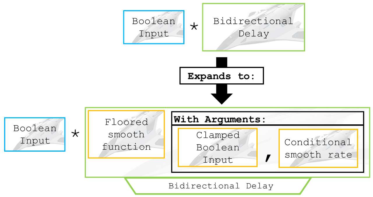
In the most basic case, the Bidirectional Delay function is multiplied by a Boolean input. When the Boolean input becomes true, the Bidirectional Delay function evaluates to be zero until the desired time has elapsed. To accomplish this, the Bidirectional Delay function employs a floored smooth function, with an argument of the aforementioned multiplied Boolean value. Figure 2.1.1 graphically displays this logic:

Figure 2.1.1: Top-Level Delay Design
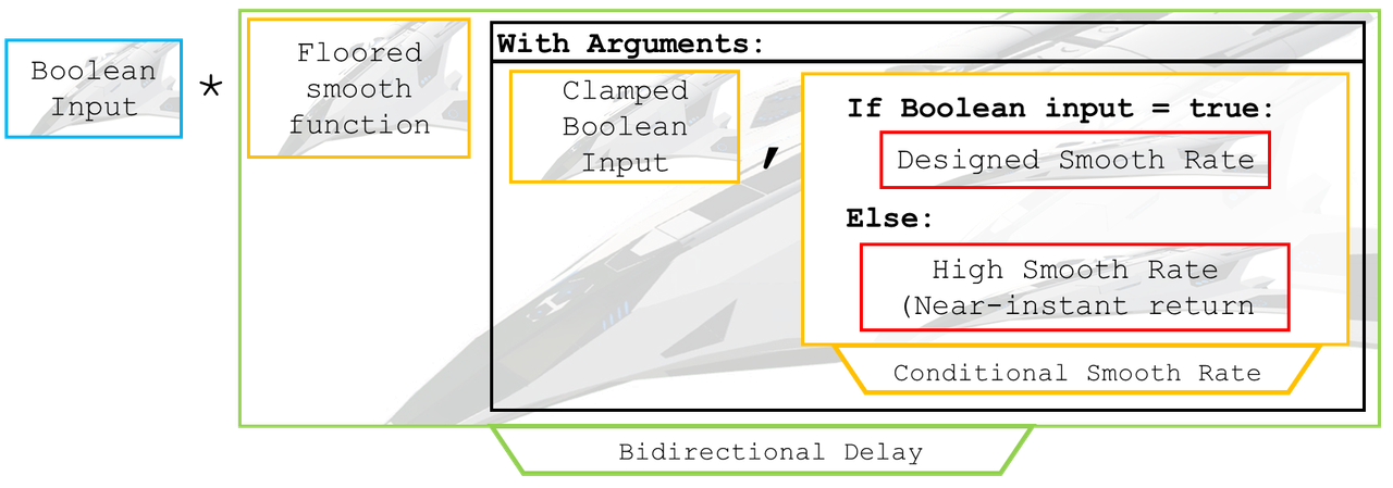
For the delay function to return to its default state when the Boolean value is false, the rate argument of the smooth function must be conditional. In other words, the smooth value must provide the desired delay only when the Boolean is true. Figure 2.1.2 expands the conditional smooth rate:

Figure 2.1.2: Expanded Delay Design
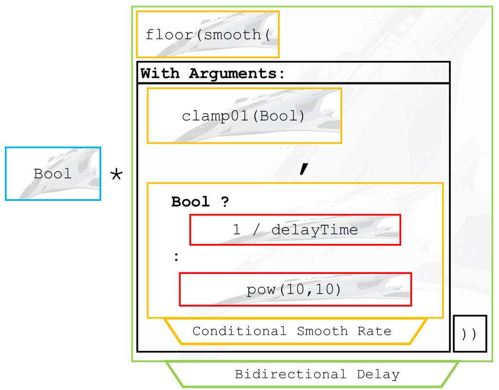
This design allows the delay to quickly return to its default state. When the smooth function is advancing, it does so at a rate specified by the programmer. Conversely, when the smooth function retreats, it will almost instantly return to its default value (a high rate allows for this). Figure 2.1.3 shows the structure of the function with proper syntax:

Figure 2.1.3: The General Bidirectional Delay Function
Note that in this case, the high return rate value is pow(10,10). This return rate will work for almost all situations.
The result is a modular delay function that performs perfectly when frequently used. The format of the function is provided below for programmers to copy and paste:
Bool * floor(smooth(clamp01(Bool), Bool ? 1 / delayTime : pow(10,10) ))
Where:
Bool = any Boolean value. It can beFireGuns,Activate1, or anything else that can only betrueorfalse.
delayTime = The desired delay time. A delay of 10 seconds, for example, would call for a delayTime of10.
For example, if the programmer wanted a gun to fire with a delay of 2 seconds, they would use the following code in the gun’s activationGroup field:
FireGuns * floor(smooth(clamp01(FireGuns), FireGuns ? 1 / 2 : pow(10, 10)))
3: The AXIS Flight System
Orbidyn-L’s foundational flight system facilitates control on the aircraft’s pitch, roll, and yaw axes. The system itself is composed of twelve thruster groups responsible for rotational control and stabilization. This system, named AXIS, will be discussed in two sections. The first discussion, of AXIS’s rotational control function, will be followed by a discussion of the system’s rotational stability code.
3.1 Rotational Control Code Architecture
AXIS facilitates rotational control by adjusting the user’s input based on the aircraft’s angular velocity and acceleration. At the highest level, the code takes the form of the user input, multiplied by the angular velocity and acceleration control functions. Figure 3.1.1 demonstrates this top-level code structure:

Figure 3.1.1: Top-Level Rotational Control Code
Angular speed is regulated by setting a maximum value that, when reached, will cause the entire function to evaluate to zero. For a better user experience, a sensitivity factor is multiplied to the angular speed value. This sensitivity factor lets the user adjust the maximum angular velocity of their aircraft mid-flight.
Angular acceleration is controlled in a nearly identical fashion. It is important to note, though, that angular acceleration is only limited when the aircraft is rotating in a relevant direction. Testing has confirmed that this conditional clause enhances the flight experience accompanied by the AXIS system. Figure 3.1.2 shows the expansion of the angular speed and acceleration control functions:

Figure 3.1.2: Rotational Code Expansion
Based on the user’s input, the sensitivity factor can be greater or less than one. After all, a fractional factor will decrease the system’s regulated angular rates, while a factor of two, for example, will double the system’s regulated angular rates. Figure 3.1.3 demonstrates conceptually how the sensitivity factor can decrease or increase, which completes the full expansion of the code’s architecture:

Figure 3.1.3: Complete Rotational Control Code Design
Practically, the sensitivity factor is regulated by the user’s trim input. A nested conditional statement is therefore necessary for the factor to work properly. Figure 3.1.4 shows the code in proper syntax, with code taken from a roll thruster group:

Figure 3.1.4: Roll Thruster Example
It is simply impractical to provide a general formula for this entire system. Instead, the code for each thruster group will be provided below for copying and pasting:
Roll Left Thruster Group: -1 * Roll * clamp01(RollRate < 270 * (Trim = 0 ? 1 : (sign(Trim) = 1 ? 1 + 0.5 * Trim : 1 + 5/6 * Trim)) ) * clamp01(sign(RollRate) = 1 ? clamp01(rate(rate(Roll)) < 5760 * (Trim = 0 ? 1 : (sign(Trim) = 1 ? 1 + 0.5 * Trim : 1 + 5/6 * Trim)) ) : 1)
Roll Right Thruster Group: Roll * clamp01(RollRate > -270 * (Trim = 0 ? 1 : (sign(Trim) = 1 ? 1 + 0.5 * Trim : 1 + 5/6 * Trim)) ) * clamp01(RollRate <= 0 ? clamp01(rate(rate(Roll)) > -5760 * (Trim = 0 ? 1 : (sign(Trim) = 1 ? 1 + 0.5 * Trim : 1 + 5/6 * Trim)) ) : 1)
Pitch Up Thruster Group: -1 * Pitch * clamp01(PitchRate > -180 * (Trim = 0 ? 1 : (sign(Trim) = 1 ? 1 + 2 * Trim : 1 + 5/6 * Trim)) ) * clamp01(PitchRate <= 0 ? clamp01(rate(rate(Pitch)) > -180 * (Trim = 0 ? 1 : (sign(Trim) = 1 ? 1 + 2 * Trim : 1 + 5/6 * Trim)) ) : 1)
Pitch Down Thruster Group: Pitch * (PitchRate < 180 * (Trim = 0 ? 1 : (sign(Trim) = 1 ? 1 + 2 * Trim : 1 + 5/6 * Trim)) ) * (sign(PitchRate) = 1 ? clamp01(rate(rate(Pitch)) < 180 * (Trim = 0 ? 1 : (sign(Trim) = 1 ? 1 + 2 * Trim : 1 + 5/6 * Trim)) ) : 1)
Yaw Left Thruster Group: -1 * Yaw * clamp01(YawRate > -360 * (Trim = 0 ? 1 : (sign(Trim) = 1 ? 1 + 2 * Trim : 1 + 7/8 * Trim)) ) * clamp01(YawRate <= 0 ? clamp01(rate(rate(Yaw)) > -720 * (Trim = 0 ? 1 : (sign(Trim) = 1 ? 1 + 2 * Trim : 1 + 7/8 * Trim)) ) : 1)
Yaw Right Thruster Group: Yaw * clamp01(YawRate < 360 * (Trim = 0 ? 1 : (sign(Trim) = 1 ? 1 + 2 * Trim : 1 + 7/8 * Trim)) ) * clamp01(sign(YawRate) = 1 ? clamp01(rate(rate(Yaw)) < 720 * (Trim = 0 ? 1 : (sign(Trim) = 1 ? 1 + 2 * Trim : 1 + 7/8 * Trim)) ) : 1)
Note that each thruster should be placed in a position that will allow it to apply torque in its respective direction. Different angular velocities work better for different kinds of rotations. A minimum of one thruster per group is necessary. Each thruster should provide more torque than its respective rotational stability thruster, which will be discussed next (in Section 3.2).
3.2 Facilitating Rotational Stability
The objective of AXIS’s rotational stabilization system is to counteract unwanted aircraft rotation. As a result, the aircraft remains stable (and controllable) in flight. Six separate thruster groups are used to accomplish this function. Effectively, each thruster works to “zero” the aircraft’s angular velocity on its roll, pitch, and yaw axes.
The code used in this application is simple when compared to the previously discussed rotational control code (Section 3.1). At the highest level, each thruster is coded to counteract rotation on its respective axis. In the case of a negligible (that is - a nonzero, but unnoticeable) angular velocity, each thruster is also programmed to not attempt to perform any unnecessary corrections.
The code expands minimally, by including a conditional statement in the thruster’s “zero angular velocity” function. Therefore, the thruster only fires if, and when, it can counteract the aircraft’s current angular velocity. Figure 3.2.1 summarizes the design of the rotational stabilization code:

Figure 3.2.1: Rotational Stabilization Code Design
In this case, it is impractical to provide a general formula for the entire system. Instead, the code for each thruster group will be provided below for programmers to copy and paste. Please note that each group is listed in terms of what motion it counters:
Counter Upward Pitch: clamp01(-1 * PitchRate / 10) * (PitchRate < 0 ? 1 : 0)
Counter Downward Pitch: clamp01(PitchRate / 10) * (PitchRate > 0 ? 1 : 0)
Counter Leftward Roll: clamp01(RollRate / 10) * (RollRate > 0 ? 1 : 0)
Counter Rightward Roll: clamp01(-1 * RollRate / 10) * (RollRate < 0 ? 1 : 0)
Counter Leftward Yaw: clamp01(-1 * YawRate / 10) * (YawRate < 0 ? 1 : 0)
Counter Rightward Yaw: clamp01(YawRate / 10) * (YawRate > 0 ? 1 : 0)
It is important to note that each thruster should be placed where it can apply torque in its respective direction. This torque should be smaller than the torque provided by the rotational control thrusters (Section 3.1). A minimum of one thruster per group is required.
4: The LUNA Flight System
The LUNA system supplies lift to the aircraft regardless of its velocity or orientation. To accomplish this function, the system applies a force onto the aircraft, that counters the effects of gravity. A six-thruster system configuration accomplishes this objective without the use of any moving parts.
4.1 Describing "Down" in a Rotating Reference Frame
The reference frame of an aircraft rotates along two axes of interest, which are, in this case, the pitch and roll axis. The direction of gravity, then, must be derived from a rotation of the aircraft’s reference frame. Specifically, a rotation consisting of combined pitch and roll rotations will be considered.
Two rotations (one rotation on the pitch and roll axis, respectively), call for two projection operations. Trigonometry can be used to project the direction of gravity onto the aircraft’s vertical, longitudinal, and lateral axes.
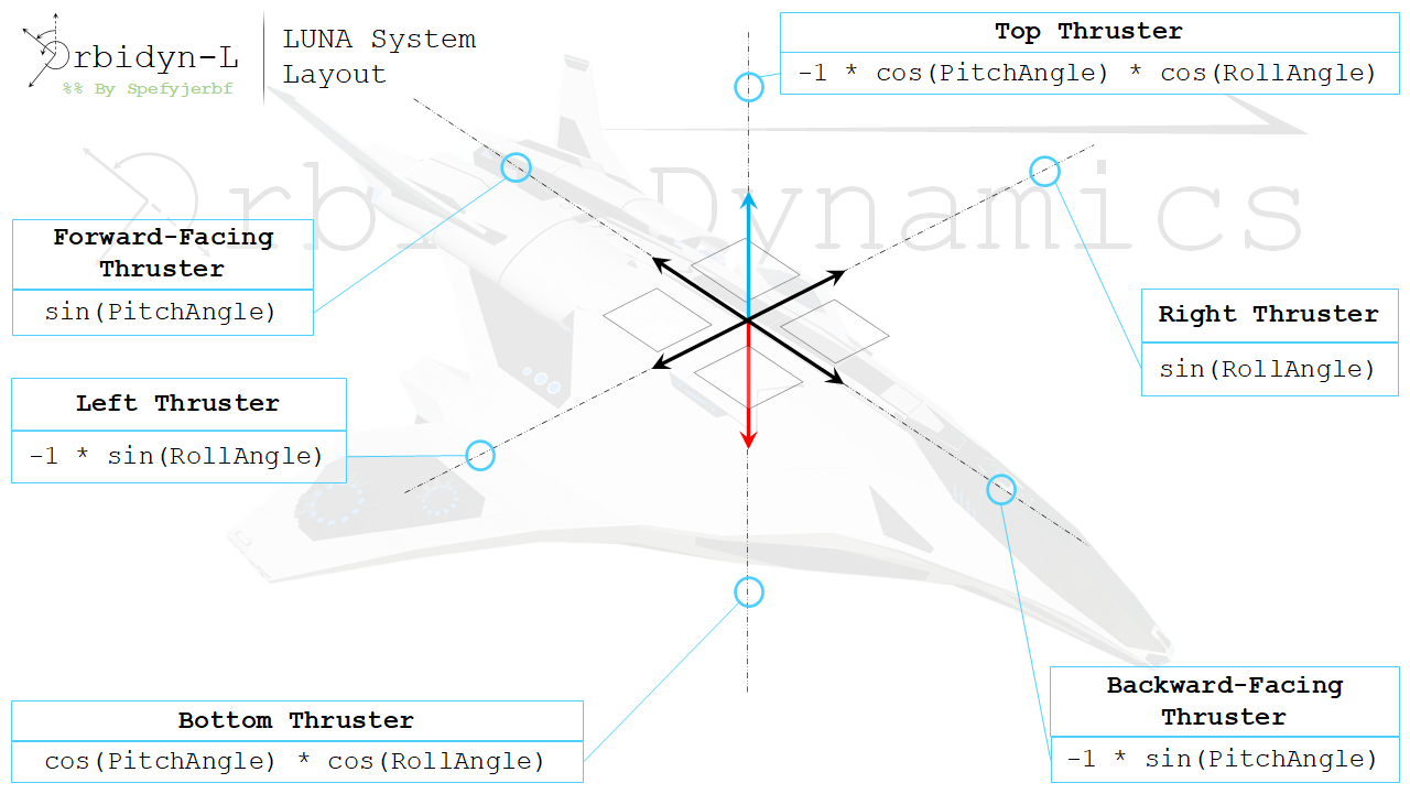
This approach must be modified for use in a six-thruster system. In this case, negation is applied as needed to thrusters that face a “negative” direction. Figure 4.1.1 displays the results of the discussed trigonometric operations, in the form of code used by the LUNA system:

Figure 4.1.1: Thruster Positioning and Code
The code is simple, but the thrusters require some extra setup to operate properly. The next section (Section 4.2) will discuss the details of LUNA thruster setup. In the meantime, each thruster’s code is provided below for programmers to copy and paste:
Top Thruster: -1 * cos(PitchAngle) * cos(RollAngle)
Bottom Thruster: cos(PitchAngle) * cos(RollAngle)
Forward-Facing Thruster: sin(PitchAngle)
Backward-Facing Thruster: -1 * sin(PitchAngle)
Right Thruster: sin(RollAngle)
Left Thruster: -1 * sin(RollAngle)
4.2 Implementation and AXIS Integration
The LUNA system’s code is quite simple, but its thrusters require some extra setup to function as needed. Each thruster must be configured according to the following specifications:
Engine type: Blasto J15 (the smallest jet engine)
Max input: 0.01 (Enter this in the
maxfield underinputController)
The powerMultiplier, too, must be configured according to the formula: 100 * W / 3,372
Where:
W = aircraft weight (pound-force). It is the value displayed in the designer as lbs.
3,372 is the force rating of the Blasto J15 engine.
When used together, the previously discussed AXIS system disrupts the normal operation of the LUNA system. The culprit behind this disruption is AXIS’s failure to apply a net force of zero in its basic configuration. Therefore, a minor adjustment in the AXIS system is required before it can cooperate with the LUNA system.
Each AXIS thruster group should include two thrusters on opposing sides of the aircraft. Therefore, the AXIS system will require 24 individual thrusters when it is installed alongside a LUNA system. With this modification, a net force of zero will result from normal AXIS system operation; the LUNA system’s function will therefore not be undermined by AXIS integration.
Oh boy, that was a long description. If you even read a fraction of it, then I greatly appreciate you. Special thanks to SPMC for some general feedback, and for helping me debug my (very barebones) screenshot mod!

For the Luna system the code for the forward and backwards thrusters and swapped
Return link to Orbidyn-L: Link
@LobsterBisque128 I didn’t know that, thanks for letting me know!
Thanks @spefyjerbf
@LobsterBisque128 loaded weight
For weight do I use empty weight to r loaded weight
How you learn funky trees system
@WereOutOfNamesArentWe LUNA should work on any aircraft. As long as you follow the instructions, you should be fine. If you run into any problems, feel free to ask too.
.
This system is free for anyone to use - just give appropriate credit wherever applicable!
@FireFast212 No problem!
@spefyjerbf thx!
@FireFast212 Smooth limits how fast a value changes. It lets you designate a rate for the change of the value.
@spefyjerbf ok. also what does Smooth mean (in funky trees)
@FireFast212 It “clamps” whatever is in the parenthesis. As a result, the function will never be lower than zero, or larger than 1.
@spefyjerbf i know. what does it mean?
@FireFast212 clamp01 is a function used in Funky Trees.
What does Clamp01 mean?
@ThomasRoderick Yes. It can be used in many areas! Hopefully some futuristic creators decide to use this system in the future.
Just realized one thing: The LUNA system can usher in a new age of aerostats, and perhaps even starships and steam/dieselpunk fliers (a.k.a. flying battleships and carriers, e.g. @WalrusAircraft). Yeah I know that the Orbidyn is a small (Star Citizen-esque) starship in its own right, but I mean the larger ones, like the Hornet's Domain and the Seraph, or those warships of @Ephwurd (*sniff* may solar winds be always on his side *sniff*). Like seriously, this design allows larger ships to roll to one side to unleash a powerful broadside to enemies on a different altitude, or to pitch up or down to quickly increase/decrease its altitude.
@Alpha6 Ty! This one was really dense, but it was a joy to write.
I read the whole thing when I had nothing to do
Oh my gooooooood
@ThomasRoderick Yeah. I think my unity broke so I needed to fix it. I also had no idea how to use unity then either.
Damn. Just damn... Also, just realized that you recycled an old forum post that's about... the construction process of New Portum and how it worked (or lack thereof) with the Unity Engine?
Thanks! @spefyjerbf
@switdog08 Ah. That would be an input then.