

Lateral, longitudinal, and vertical velocities can be best described as sideways, forward/backward, and up/down speeds, respectively. These velocities are measured with respect to the aircraft, which is quite useful for use in a variety of flight systems. These velocity components have been re-derived in a fashion that does not include Angle of Attack (AoA) or Angle of Slip (AoS) data. As a result, these new formulae no longer depend on the assumption of absent wind (an assumption that was surprisingly valid for SP, but useless anywhere else).
Figure 0: A flight system successfully eliminates all aircraft velocity components
The velocity components were derived using rotation matrix methods. A coordinate system fixed on the aircraft was constructed using the columns of a modified pitch/yaw/roll rotation matrix. An inertial velocity vector, as measured from the ground, was then projected onto the aircraft-fixed coordinate system using dot product methods.
1. Code Snippets, Complete Code, and the Demonstrator
The necessary FT variable system to generate the aircraft's longitudinal (forward/backwards), lateral (sideways), and vertical (up/down) velocities is provided below:
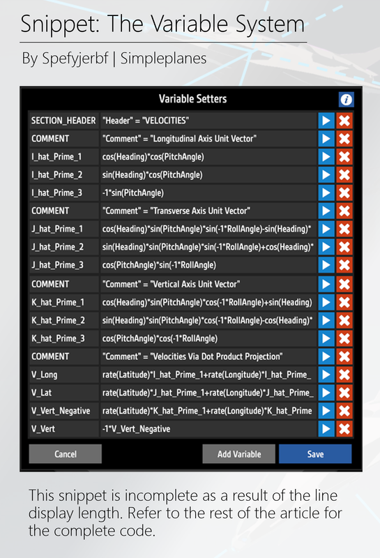
Figure 1.1: Code Snippet
Note that the above snippet is incomplete, as some lines are too long to be shown. The complete variable system is included below for easy copy/pasting:
SECTION_HEADER: "Header" = "VELOCITIES"
COMMENT: "Comment" = "Longitudinal Axis Unit Vector"
I_hat_Prime_1: cos(Heading)*cos(PitchAngle)
I_hat_Prime_2: sin(Heading)*cos(PitchAngle)
I_hat_Prime_3: -1*sin(PitchAngle)
COMMENT: "Comment" = "Transverse Axis Unit Vector"
J_hat_Prime_1: cos(Heading)*sin(PitchAngle)*sin(-1*RollAngle)-sin(Heading)*cos(-1*RollAngle)
J_hat_Prime_2: sin(Heading)*sin(PitchAngle)*sin(-1*RollAngle)+cos(Heading)*cos(-1*RollAngle)
J_hat_Prime_3: cos(PitchAngle)*sin(-1*RollAngle)
COMMENT: "Comment" = "Vertical Axis Unit Vector"
K_hat_Prime_1: cos(Heading)*sin(PitchAngle)*cos(-1*RollAngle)+sin(Heading)*sin(-1*RollAngle)
K_hat_Prime_2: sin(Heading)*sin(PitchAngle)*cos(-1*RollAngle)-cos(Heading)*sin(-1*RollAngle)
K_hat_Prime_3: cos(PitchAngle)*cos(-1*RollAngle)
COMMENT: "Comment" = "Velocities Via Dot Product Projection"
V_Long: rate(Latitude)*I_hat_Prime_1+rate(Longitude)*I_hat_Prime_2+rate(-1*Altitude)*I_hat_Prime_3
V_Lat: rate(Latitude)*J_hat_Prime_1+rate(Longitude)*J_hat_Prime_2+rate(-1*Altitude)*J_hat_Prime_3
V_Vert_Negative: rate(Latitude)*K_hat_Prime_1+rate(Longitude)*K_hat_Prime_2+rate(-1*Altitude)*K_hat_Prime_3
V_Vert: -1*V_Vert_Negative
A demonstrator, pre-programmed with this variable system, is also available here. The longitudinal, lateral, and vertical velocities are defined as V_Long, V_Lat, and V_Vert, respectively. Note that the code has been commented by assigning a string (converted to a boolean) to a variable named COMMENT. While the code can be written as a single line for each velocity, it is recommended to use the code as it is currently written. Intermediate variables, such as the longitudinal, lateral, and vertical unit vectors, may be useful within a larger overall flight system implementation.
2. Limitations of Previous Flight Systems
Previous expressions for lateral, longitudinal, and vertical velocities were simple, but would fail under the presence of wind. These expressions used projection methods based wholly on trigonometry, with an argument related to AoA or AoS. With the condition of stagnant air, the total velocity could be easily decomposed into components using the described method.
The method, though, becomes invalid when wind is present. AoA and AoS, when wind is present, are functions of both the aircraft's velocity and the ambient wind conditions. Therefore, the lateral, longitudinal, and vertical velocity components fail with the presence of wind. A new expression, that does not use AoA or AoS angles, is needed to overcome this wind-related limitation.
3. The Mathematical Discussion
The lateral, longitudinal, and vertical velocity components can be found by projecting an inertial velocity vector onto the aircraft's principal axes. This section is, for purposes of this article, an explanation of this method. This discussion will most likely not be a complete mathematical derivation, but it will provide the necessary mathematical basis for the formulation of an aircraft's lateral, longitudinal, and vertical velocity components.
3.1 Constructing the Relevant Coordinate Systems
Two coordinate systems must be constructed to solve the velocity component problem. First, an inertial (ground-fixed) coordinate system is readily available with some manipulation. Latitude, Longitude, and Altitude information can be used to construct a left-hand coordinate frame, but a right-hand coordinate frame is necessary for successful vector projection. Therefore, the components of the inertial frame can be described as follows:
i = Direction of Latitude
j = Direction of Longitude
k = Down Direction
A particularly experienced reader may notice that this coordinate system is similar to a North-East-Down (NED) reference frame. Note that the inversion of the vertical axis will necessitate a similar sign inversion for the aircraft's roll angle.
The aircraft's longitudinal, lateral, and vertical unit vectors can be derived using a rotation matrix; the resulting axes are collectively referred to as the aircraft's principle axes. The columns of a standard yaw/pitch/roll rotation matrix define these principal axes within the scope of this velocity problem. Therefore, an aircraft-fixed coordinate system is defined using pitch, roll, and yaw angles, as shown below. Note that the new, rotated coordinate system is denoted by i', j', and k' unit vectors:
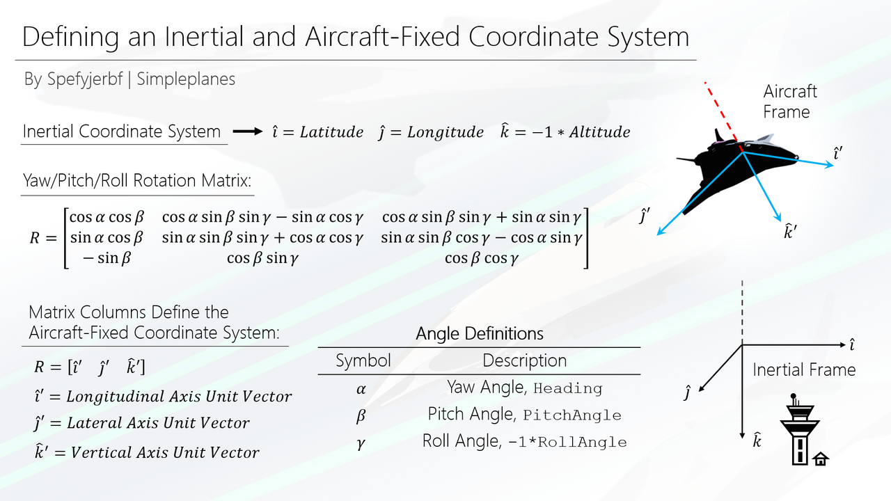
Figure 3.1.1 Defining the coordinate systems
3.2 A Component-Level Projection Method
Four vectors of interest - each existing within 3D Cartesian Space - are available to complete a set of projection operations. The aircraft's velocity vector is available as measured from an inertial observer. Unit vectors representing the aircraft's lateral, longitudinal, and vertical axes are also available. The aircraft's lateral, longitudinal, and vertical velocities, then, can be found by projecting the velocity vector onto each of the aircraft's principal axes.
The chosen projection method produces the component of the velocity vector, along each principal axis. This operation is completed by dividing the dot product of the velocity and principal axis vectors, by the magnitude of the principal axis vector. The principal axis vectors, though, are unit vectors (magnitude of one). Therefore, the operation can be completed by simply taking the dot product of the velocity and principal axis vectors. The figure below illustrates the discussed methods, as well as their results:
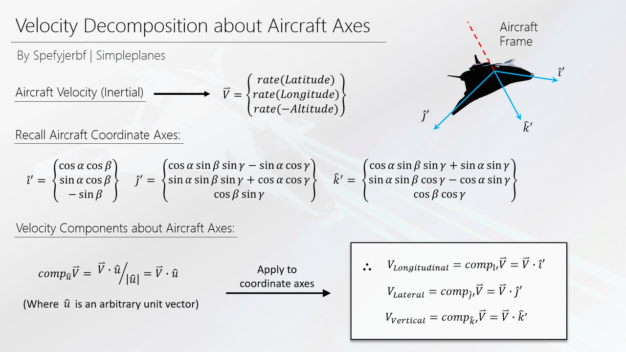
Figure 3.2.1 Aircraft-fixed velocity components
The results of these operations are suitable for use within a flight system. However, the right-hand coordinate system, representing the aircraft's principal axes, is somewhat counterintuitive. The vertical velocity, as produced by the projection alone, is negative when the aircraft is moving upward. Therefore, the coordinate system has been re-converted into a left-hand system by, simply, multiplying the vertical velocity by negative one. Therefore, the vertical velocity, as provided within the FT code, will read as positive when the aircraft is moving upwards.
@tristan300 Hey thanks for asking! At the moment, I do not have any builds planned for the foreseeable future. My current job is quite similar to SP, so I have been branching out into other games/hobbies. I do still check the site from time to time though
Do u maybe still make Planes or did u completly Stop because i Love Ur builds and yea with all the new players and the soon Release of sp2 maybe wanna build a final Project?
@spefyjerbf how do I pronounce your username
@spefyjerbf @Sadboye12 your builds inspired me to keep playing simpleplanes and reached to a point where i can finally make my own builds
@Mousewithamachinegun123 @DISHWASHER2005 @TTL Thank you! It was fun to build them, though I don't plan to build much in the future.
@DISHWASHER2005
me three!
@16 agreed
@spefyjerbf man I miss your builds…
Just out of boredom decided to run debug expressions...
Found:
1) V_Long value is simillar to
TAS/GSandSpeedlocal variable of cokpits and F.C. (flight computer part)2) V_Lat value is simillar to
AngleOfSlip3) V_Vert value is simillar to
AngleOfAttackConclusion:
Probably, it is possible to get AoA and AoS for a local cockpit or F.C.
@11qazxc Did it not work at very high altitudes? If the accuracy of altitude degrades with increasing altitude, then there’s not much that can be done about that - that issue would be the result of how SP itself is programmed, rather than my code
It looks nice, but a bit too idealized. Yesterday i was trying to fly in space (200km ASL) and rate(Altitude) did not really work because position was as accurate as in minecraft, and i don't want to use AoA/AoS (i don't like to fly relative to wind even if there's no air). Do you have any recommendations for such situation?
Ok @spefyjerbf
@FuriousChicken My current job satisfies my need for engineering design, so I don’t really have any builds planned at the moment. I still browse the site every once in a while though
Where are you? @spefyjerbf
yay their back! i missed u!
@Dathcha my brain cells.exe have stopped working
@Bobyo bro same
Them equations are horrifying
This might come in handy later on, for me.
slowly backs away
@spefyjerbf This sounds feasible. It would be long. I found a neat storage function which might help. Heck using this on a plane means you should also take into account all the other forces of wings, drag, torque, etc. Makes it into one giant physics problem XD
@OrderlyHippo You would choose C (in both integrations) to match the aircraft’s initial conditions at time=0.
.
In other words, after your first integration, you will have an expression for velocity, plus C. C really just depends on the initial velocity, so if you plug in your initial velocity at time=0, you can solve for the correct C value.
.
When you have found C after your first integration, integrate again for position. You will get another + C. Substitute your initial position at time=0 to solve for the correct C, which will result in a correct position expression.
@spefyjerbf Acceleration seems feasible in SP. When finding integrals, a constant is added. Does time go there? You said find the integral twice. So what is 'c' for the second one? I have an exam on this tomorrow and I haven't studied so forgive me if i'm horribly incorrect lol
@OrderlyHippo In this case, the term "inertial" means that the velocity is measured by an observer that is not moving. So, "inertial" velocity is what someone on the ground would measure if they took a speed reading of the plane.
.
A navigation system that would use something like inertia (as in the physical property) would measure the acceleration of the aircraft, and integrate it twice to get a position. A good amount of guidance systems have used this principle, including some early ICBMs. I'm not sure how such a system would be implemented in SP though.
You said, “inertial velocity vector.” Does that mean what I think it means? It would be possible to have an auto pilot system based on inertia?instead of angles? Like instead of trig? Does this use integrals? I’m curious